Place of Origin:
shenzhen China
Brand Name:
dothinkey
Certification:
CE
Model Number:
MAX9296
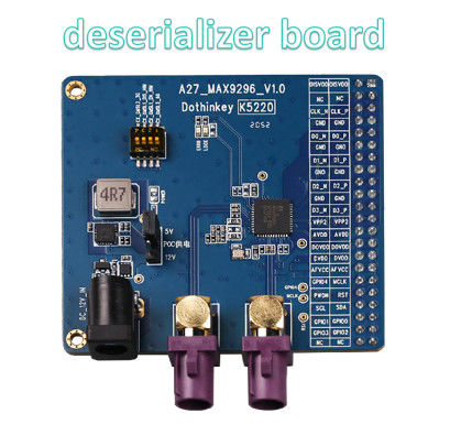
(1) About POC power supply: The decoder board can use two power supply modes of DC socket or test box for POC power supply (selected by J6), wherein when DC socket power supply is selected, the decoder board needs to connect an external 12V/1A power adapter separately, and then select 12V or 5V as POC power supply through J5; When selecting the power supply for the test chamber, the decoder board does not require a separate external power supply and can be configured to power the POC via the AP configuration (in which case the J5 jump cap fails), and for the UC930 test chamber, the POC supply range can be set from 4V to 18V. The position of J5 and J6 is shown in the figure below, our factory default setting is the 5V output of the DC socket (so as not to burn out the client module), users should choose the appropriate POC power supply according to the actual power supply requirements of the module under test before use.
(2) About the power supply of the decoder board chip: The MAX9296 chip on this decoder board needs to be externally set up with four power supplies, and the four power supplies must be powered by the test box, wherein AFVCC and DVDD must be fixed at 1.2V at the AP end, AVDD must be fixed at 1.8V at the AP end, DOVDD must be set in the range of 1.8-3.3V as needed, if there are other voltage settings in the AP, please ignore. Before the drawing is made, it must be ensured that the voltage of these channels is not set to the specified range to avoid damage to the MAX9296 chip.
(3) About the interface: The decoder board has reserved a 2.54mm pitch, dual-row 44PIN pin header for docking with the standard MIPI interface of our test box products.
(4) About MAX9296: According to official information, MAX9296 can theoretically be paired with a variety of GMSL1/GMSL2 serializers, and when paired with different GMSL serializers, different register parameter groups need to be configured.
(5) About the DIP switch: The DIP switch of the decoder board is a 4-in-1 DIP switch, each represents an independent hardware setting, each hardware setting corresponds to a special function of the power-on initialization register setting, only one DIP bit is allowed to be set to the "ON" position at a time, and after each DIP bit is set, the Decoder Board needs to be re-powered to make this setting take effect.
Send your inquiry directly to us